Table of Contents
Taking apart the ReinerSCT nPA RFID Basisreader
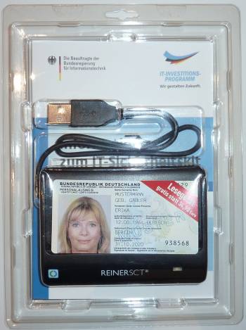
The ReinerSCT basis reader is a pretty basic reader for mifare cards and the new german ident-card (ePA or nPA). It was sold with german computer-magazine ComputerBild 26/2010 for €3,70 instead of the retail €34,90. It comes with a OWOK rfid card. There is a thread on german µC-related forums Mikrocontroller.net discussing the hackability of this reader as well.
Someone did a nice writeup on the details of the OWOK-card that comes with the reader (german), and here's another teardown.
The package
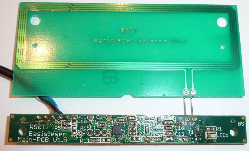
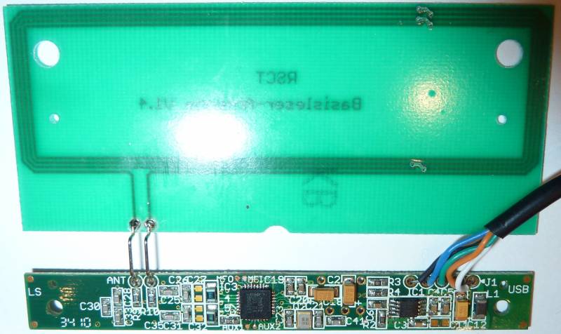
The device
The chips
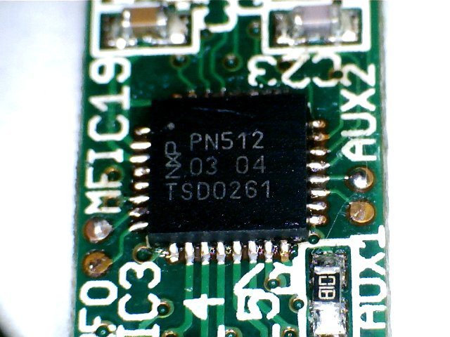
| NXP PN512 (RFID transceiver, datasheet) |
|---|
| package: HVQFN32 (SOT617-1) |
 |
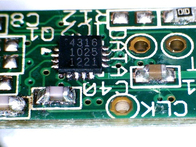
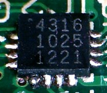
| Cypress CY7C64316 (datasheet), implements the USB CCID → PN512 SPI interface |
|---|
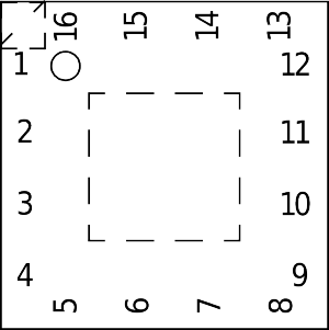
| package: HVQFN16 (SOT758-1) |
 |
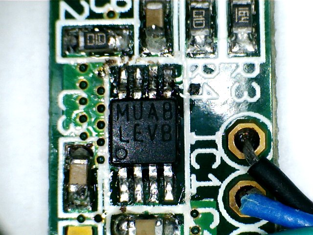
| NSC LP3982 (LP3982IMM-ADJ) (datasheet) (5V → 3.3V voltage regulator) | |
|---|---|
| package marking: MUA8 / LEVB | package: 8-Pin MSOP/MINI-SOIC |
 |
|
Connection between the chips
The reader uses the SPI mode of the NXP PN512, and some of the signals go to testpoints (note that they are swapped). The testpoints are for ISSP programming of the PSoC (needs DATA, CLK, RESET (XRES), GND and VCC).
| signal | pin on the 4316 | pin on the PN512 | testpoint |
|---|---|---|---|
| MISO | 3 | 31 (D7) | |
| MOSI | 4 | 30 (D6) | CLK |
| SCLK | 9 | 29 (D5) | DATA |
| nCS | 2 | 24 (ALE) | |
| IRQ | 13 | 23 (IRQ) | |
| NRSTPD | 10 | 6 (NRSTPD) |
The PSoC microcontroller (Cypress CY7C64316)
For handling the USB connection and controlling the RFID transceiver, the reader uses a Cypress PSoC microcontroller. There is a free (windows-only) IDE with built-in C-Compiler available. For more information see the datasheet as well as the Technical Reference Manual.
Specs:
- 32KB flash
- 2KB RAM
- M8C architecture
- There is an open-source assembler for this architecture called m8cas, which is part of m8cutils
- contains a disassembler as well, m8cdas
- There's another disassembler called m8cdis: forum post, code
- GRAS, the Generic Assembler, supports the m8c as well
- Yet another assembler, GPLv2 bootloader, USB code here
- internal oscillator with up to 24MHz
- supports ISSP (in-system serial programming)
Notes:
- m8cprogs, as part of m8cutils, contains schematics for various programmers,
but it is unclear yet if it works with the enCoRe V series of PSoCs (to which the CY7C64316 belongs to) - the Cypress CY3210 MiniProg1 supports the CY7C64316
- I hacked m8cprog to support the chip, by sniffing what the MiniProg1 does, so it is now possible to flash custom code via ISSP without the need for a quite expensive MiniProg1
- Get the code here
- With a few tricks I was able to dump the firmware
Initialization of the PN512
- pn512.c
/* NXP PN512 initialization
 * this was obtained by sniffing the communication between the PN512 and the
 * CY7C64316 in the ReinerSCT Basisreader, and decoding it with the datasheet.
 *
 * (C) 2010 by Steve Markgraf <steve@steve-m.de>
 *
 * All Rights Reserved
 *
 * This program is free software; you can redistribute it and/or modify
 * it under the terms of the GNU General Public License as published by
 * the Free Software Foundation; either version 2 of the License, or
 * (at your option) any later version.
 *
 * This program is distributed in the hope that it will be useful,
 * but WITHOUT ANY WARRANTY; without even the implied warranty of
 * MERCHANTABILITY or FITNESS FOR A PARTICULAR PURPOSE.  See the
 * GNU General Public License for more details.
 *
 * You should have received a copy of the GNU General Public License along
 * with this program; if not, write to the Free Software Foundation, Inc.,
 * 51 Franklin Street, Fifth Floor, Boston, MA 02110-1301 USA.
 *
 */

#define CommandReg	0x01
#define CommIEnReg	0x02
#define DivIEnReg	0x03
#define CommIRqReg	0x04
#define ErrorReg	0x06
#define Status2Reg	0x08
#define FIFOLevelReg	0x0a
#define ControlReg	0x0c
#define ModeReg		0x11
#define TxControlReg	0x14
#define TxAutoReg	0x15
#define TxSelReg	0x16
#define RxSelReg	0x17
#define RxThresholdReg	0x18
#define DemodReg	0x19
#define MifNFCReg	0x1c
#define ManualRCVReg	0x1d
#define TypeBReg	0x1e

#define ModWidthReg	0x24
#define RFCfgReg	0x26
#define GsNOnReg	0x27
#define CWGsPReg	0x28
#define ModGsPReg	0x29
#define WaterLevelReg	0xbh
#define ControlReg	0xch

#define TModeReg	0x2a
#define TPrescalerReg	0x2b
#define TReloadRegH	0x2c
#define TReloadRegL	0x2d

/* CommandReg bits */
#define RcvOff		(1 << 5)
#define PowerDown	(1 << 4)

/* CommIEnReg bits */
#define TimerIEn	(1 << 0)

/* DivIEnReg bits */
#define IRQPushPull	(1 << 7)

/* Status2Reg bits */
#define TempSensClear	(1 << 7)

/* FIFOLevelReg bits */
#define FlushBuffer	(1 << 7)

/* ControlReg bits */
#define TStopNow	(1 << 7)
#define TStartNow	(1 << 6)
#define WrNFCIDtoFIFO	(1 << 5)
#define Initiator	(1 << 4)

/* ModeReg bits */
#define TxWaitRF	(1 << 5)
#define PolSigin	(1 << 3)
#define CRCPreset	(1 << 0)

/* TxControlReg */
#define InvTx2RFOn	(1 << 7)
#define InvTx1RFOn	(1 << 6)
#define InvTx2RFOff	(1 << 5)
#define InvTx1RFOff	(1 << 4)
#define Tx2CW		(1 << 3)
#define CheckRF		(1 << 2)
#define Tx2RFEn		(1 << 1)
#define Tx1RFEn		(1 << 0)

/* TxAutoReg bits */
#define Force100ASK	(1 << 6)

unsigned int pn512_read(uint8_t reg)
{
	/* spi_read() should handle 8-bit SPI-reads */
	spi_write((1 << 7) | (reg << 1));
	return spi_read();
}

void pn512_write(uint8_t reg, uint8_t data)
{
	/* spi_write() should handle 8-bit SPI-writes */
	spi_write(reg << 1);
	spi_write(data);
}

void pn512_init(void)
{
	pn512_write(CommIEnReg, 0x00);
	pn512_write(GsNOnReg, 0xfe);
	pn512_write(CWGsPReg, 0x3f);
	pn512_write(ModGsPReg, 0x12);
	pn512_write(TxControlReg, 0x00);

	/* turn off analog part of the receiver */
	pn512_write(CommandReg, RcvOff);

	pn512_write(FIFOLevelReg, FlushBuffer);
	pn512_write(DivIEnReg, IRQPushPull);

	/* stop timer */
	pn512_write(ControlReg, TStopNow | Initiator);

	/* write the timer prescaler, which is split in 2 registers */
	pn512_write(TModeReg, 0x02);
	pn512_write(TPrescalerReg, 0x02);

	/* write the timer reload value */
	pn512_write(TReloadRegH, 0x00);
	pn512_write(TReloadRegL, 0x34);

	/* route the timer interrupt to the IRQ pin */
	pn512_write(CommIEnReg, TimerIEn)

	pn512_write(CommIRqReg, 0x7f);
	pn512_write(WaterLevelReg, 0x21);

	/* start timer */
	pn512_write(ControlReg, TStartNow | Initiator);

	/* could be triggered by PN512 timer interrupt as well */
	delay_ms(5);

	pn512_read(CommIRqReg);
	pn512_read(ErrorReg);

	pn512_write(Status2Reg, TempSensClear);
	pn512_write(ModeReg, TxWaitRF | PolSigin | CRCPreset);

	/* force ASK modulation */
	pn512_write(TxAutoReg, Force100ASK);

	/* Tx1, Tx2 and SIGOUT pin = Modulation signal from internal encoder */
	pn512_write(TxSelReg, 0x14);

	/* input of contactless UART = Modulation signal from analog part */
	pn512_write(RxSelReg, 0x88);

	/* set bit decoder tresholds */
	pn512_write(RxThresholdReg, 0x84);

	pn512_write(DemodReg, 0x4d);
	pn512_write(MifNFCReg, 0x62);
	pn512_write(ManualRCVReg, 0x00);
	pn512_write(TypeBReg, 0x00);
	pn512_write(ModWidthReg, 0x1d);

	/* rx gain 33dB, VRx [Vpp] ∼0.17 */
	pn512_write(RFCfgReg, 0x48);

	/* start TXing the 13.56MHz energy carrier */
	pn512_write(TXControlReg, InvTx2RFOn | Tx2RFEn | Tx1RFEn);

	pn512_write(ControlReg, TStopNow | Initiator);

	/* change the timer prescaler, which is split in 2 registers */
	pn512_write(TModeReg, 0x02);
	pn512_write(TPrescalerReg, 0xa5);

	/* change the timer reload value */
	pn512_write(TReloadRegH, 0x01);
	pn512_write(TReloadRegL, 0x38);

	pn512_write(CommIRqReg, 0x7f);
	pn512_write(ControlReg, TStartNow | Initiator);
}
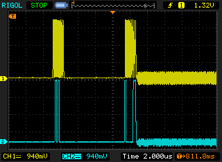
You can clearly see the increase of line noise after starting to transmit the energy carrier:
USB details
Output of 'lsusb -v':
Bus 005 Device 030: ID 0c4b:9102 Reiner SCT Kartensysteme GmbH
Device Descriptor:
  bLength                18
  bDescriptorType         1
  bcdUSB               2.00
  bDeviceClass            0 (Defined at Interface level)
  bDeviceSubClass         0
  bDeviceProtocol         0
  bMaxPacketSize0         8
  idVendor           0x0c4b Reiner SCT Kartensysteme GmbH
  idProduct          0x9102
  bcdDevice            0.01
  iManufacturer           1 REINER SCT
  iProduct                2 cyberJack RFID basis
  iSerial                 0
  bNumConfigurations      1
  Configuration Descriptor:
    bLength                 9
    bDescriptorType         2
    wTotalLength           93
    bNumInterfaces          1
    bConfigurationValue     1
    iConfiguration          0
    bmAttributes         0x80
      (Bus Powered)
    MaxPower              100mA
    Interface Descriptor:
      bLength                 9
      bDescriptorType         4
      bInterfaceNumber        0
      bAlternateSetting       0
      bNumEndpoints           3
      bInterfaceClass        11 Chip/SmartCard
      bInterfaceSubClass      0
      bInterfaceProtocol      0
      iInterface              0
      ChipCard Interface Descriptor:
        bLength                54
        bDescriptorType        33
        bcdCCID              1.10  (Warning: Only accurate for version 1.0)
        nMaxSlotIndex           0
        bVoltageSupport         1  5.0V
        dwProtocols             2  T=1
        dwDefaultClock       1000
        dwMaxiumumClock      1000
        bNumClockSupported      1
        dwDataRate           2688 bps
        dwMaxDataRate        2688 bps
        bNumDataRatesSupp.      1
        dwMaxIFSD             254
        dwSyncProtocols  00000000
        dwMechanical     00000000
        dwFeatures       000404B0
          Auto clock change
          Auto baud rate change
          Auto PPS made by CCID
          Auto IFSD exchange
          Short and extended APDU level exchange
        dwMaxCCIDMsgLen       266
        bClassGetResponse    echo
        bClassEnvelope       echo
        wlcdLayout           none
        bPINSupport             0
        bMaxCCIDBusySlots       1
      Endpoint Descriptor:
        bLength                 7
        bDescriptorType         5
        bEndpointAddress     0x83  EP 3 IN
        bmAttributes            3
          Transfer Type            Interrupt
          Synch Type               None
          Usage Type               Data
        wMaxPacketSize     0x0040  1x 64 bytes
        bInterval               5
      Endpoint Descriptor:
        bLength                 7
        bDescriptorType         5
        bEndpointAddress     0x81  EP 1 IN
        bmAttributes            2
          Transfer Type            Bulk
          Synch Type               None
          Usage Type               Data
        wMaxPacketSize     0x0040  1x 64 bytes
        bInterval               1
      Endpoint Descriptor:
        bLength                 7
        bDescriptorType         5
        bEndpointAddress     0x02  EP 2 OUT
        bmAttributes            2
          Transfer Type            Bulk
          Synch Type               None
          Usage Type               Data
        wMaxPacketSize     0x0040  1x 64 bytes
        bInterval               1
Device Status:     0x0000
  (Bus Powered)
Other readers
There are other devices (Basislesegeräte) which have been certified by the BSI:
| device | SCM SCL011 | SCM SDI011 (not yet certified) | SCM SDI010 |
|---|---|---|---|
| link | SCL011 | SDI011 | |
| type | RFID | RFID/SC dual | RFID/SC dual |
| used microcontroller | SCM STC3 | SCM STC II-B | SCM STC II-B |
| used RFID transceiver | NXP PM512HN | ? | ? |
| firmware update available | yes | no | yes |
| FCC-ID | MBPSCL011-4400 | MBPSDI011-1000 | MBPSDI010MOD02 |
| pcb pictures | yes, see link above ('Internal photos') | ||

Discussion
This paragraph offers clear idea in support of the new viewers of blogging, that truly how to do running a blog.