Table of Contents
Driving the Motorola F3 e-paper display
The Motorola F3/MOTOFONE was the first (and still is the only?) mobile phone with an e-paper display. Although this is not a pixel-based display, like found in eBook-readers (e.g. the Amazon Kindle or the B&N nook), it is still quite nice for experimenting with low power microcontroller projects.
E-paper/bistable displays have the ability to retain the display content even without the supply of power, so the initial idea I had was to build something like a clock, only powering the display when updating it every minute.
The display
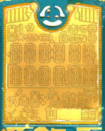
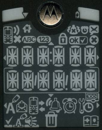
The display consists of 182 individually drivable segments, which form a row of six 14-segment characters, a row of six 8-segment characters, and many symbols used for user notification and the menu.
Display controller
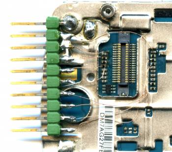
As you can see from this picture, the used display controller is a Solomon Systech SSD1621. Unfortunately there is no public datasheet, so I had to sniff the (32 bit) SPI communication between the TI Locosto baseband processor and the display. The protocol turned out not to be very difficult, just some initialization, some commands for actually writing the display content, and a command to refresh the display with the just transmitted content.
The most time has been spent for actually finding out which bit was for which segment, since all segments are wired up at random to the segment outputs of the controller. This is not surprising though, given that you need a circuit path to each and every segment - “just get them wired already, we can handle the rest in software” seemed to be the motto 
By the way, since I mentioned the TI Locosto baseband: Maybe someone wants to reverse-engineer the serial rom-bootloader of this ARM7-based processor, so we can drive the display directly from the phone 
Interfacing with the display
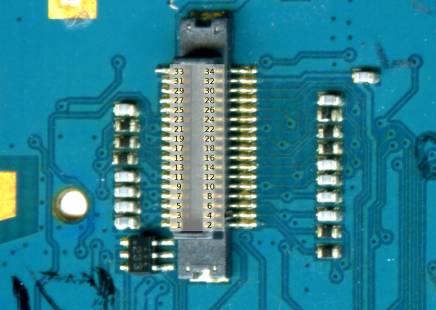
Normally, the baseband board and the display/keypad pcb are connected with a 32-pin connector (exact model unknown). Luckily there are pull-up resistors and capacitors for every needed signal, so I decided to solder some wires there, instead of directly to the connector. The schematics of this phone are floating around the web, just search for f3_schem.rar.
This is the pinout of the connector, signals that were used are highlighted:
| pin | signal | pin | signal | |
|---|---|---|---|---|
| 01 | SPKPA | 02 | TEMP_SENSOR | |
| 03 | SPKNA | 04 | DISPLAY_BUSY1 | |
| 05 | HS_SPK_CHARGE | 06 | HSMIC_OUT | |
| 07 | GND | 08 | VLED | |
| 09 | HSSPK_CHG_N | 10 | LED_C | |
| 11 | GND | 12 | DISPLAY_32K | |
| 13 | DISPLAY_BUSY0 | 14 | SYS_RESET | |
| 15 | SPI_nCS0 | 16 | SPI_CLK | |
| 17 | SPI_MOSI | 18 | SPI_MISO | |
| 19 | VIO | 20 | VBAT | |
| 21 | PWON | 22 | KBR(0) | |
| 23 | KBR(1) | 24 | KBR(2) | |
| 25 | KBR(3) | 26 | KBC(0) | |
| 27 | KBC(1) | 28 | KBC(2) | |
| 29 | KBC(3) | 30 | KBC(4) | |
| 31 | GND | 32 | PCHGAC | |
| 33 | RF_ANT | 34 | GND | |
Microcontroller
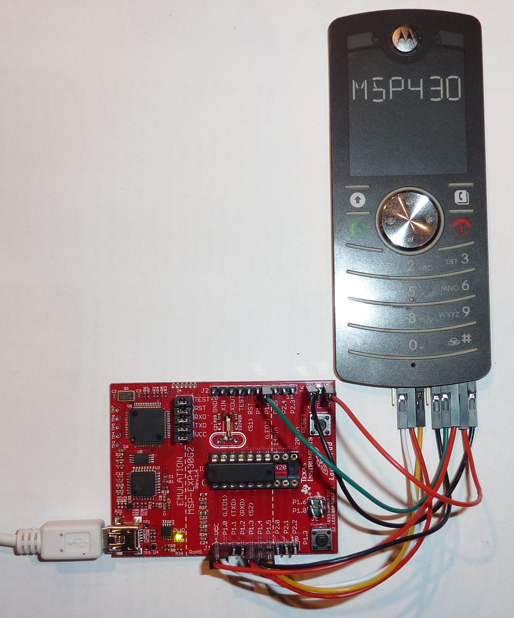
To drive the display, I'm using a TI MSP430G2231 low-power microcontroller on the TI Launchpad. The Launchpad has been populated with the external 32KHz crystal oscillator that comes with it. The connection between display and Launchpad is as follows:
| MSP430 | display | ||
|---|---|---|---|
| port | signal | pin | signal |
| P1.0 | ACLK 32KHz clock output | 12 | DISPLAY_32K |
| P1.1 | display supply | 19+20 | VIO+VBAT |
| P1.2 | busy input | 04 | DISPLAY_BUSY1 |
| P1.3 | display reset | 14 | SYS_RESET |
| P1.4 | SPI slave-select | 15 | SPI_nCS0 |
| P1.5 | SPI clock | 16 | SPI_CLK |
| P1.6 | SPI MOSI | 17 | SPI_MOSI |
Note: even though the MISO signal is connected in the original phone, there's no activity at all, so I left it unconnected. Also, DISPLAY_BUSY0 and 1 seem to be identical.
Video
I've uploaded a video, demonstrating the display and Launchpad being used as a low-power clock.
A few notes on the video:
- The timer has been sped up by the factor of 10 for demonstration purposes, so 1 minute on the clock is actually 6 seconds in the video.
- Completely powering down the display also has its disadvantages. As you can see, the display needs to be initialized every time you power it up again (thus the flickering), which isn't needed when just disabling the 32KHz clock.
- The second row (showing 000000) is just a counter, counting the total hours, and is intended for a runtime test with a goldcap or CR2032 battery.
Sourcecode
The sourcecode can be found on github: https://github.com/steve-m/epaperclock, and can be cloned with
git clone git://github.com/steve-m/epaperclock.git
I used msp430-gcc 4.4.5 to compile the code, and mspdebug 0.14 for flashing it. There's a great how-to on Hackaday: Launchpad programming with Linux
